C481 B581 Computer Graphics
Dana Vrajitoru
Introduction to 3D Graphics
3D Graphics
-
The displayed objects have 3 dimensions: width (x), height (y), and depth
(z).
-
Classification
-
Real-time versus pre-rendered animation
-
Immediate versus retained mode
-
3D Effects:
-
perspective, hidden surfaces
-
color, shading, transparency, texture mapping
-
The collection of geometrical objects defined in the program in usually
called the scene.
Coordinate Systems
-
2D - Cartesian coordinates Oxy.
-
Viewport: region of the application window used for drawing.
-
3D Cartesian coordinates Oxyz.
-
Vertex: a position in the 3D space - a vertex.
-
Most 3D APIs use real 3D coordinates
-
Going from the physical 3D coordinates to the 2D discrete screen coordinates
- projection.
Projection
Def. P(x, y, z) -> P'(x', y', z') in the projection plane p.
Usually the projection plane is defined by z'=0.
2 types of projection: parallel, perspective.
Parallel projection: orthographic or oblique.
The parallel projection
-
Defined by a projection line (direction) d.
-
If the line is perpendicular to the projection plane - orthographic projection.
Otherwise oblique.
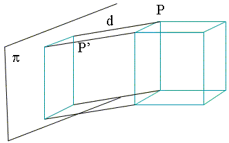
Features of the parallel projection:
-
preserves the ratio between parallel objects;
-
preserves the parallel lines;
-
the orthogonal projection preserves the width of segments that are parallel
to p;
-
gives poor impression of image depth;
-
often used for technical drawing, architecture plans, etc.
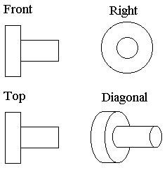
The perspective projection: from a projection center C representing
the viewer's eye.
-
Given a projection center C representing the viewer's eye.
-
Consider the line L connecting C and P.
Then P' = intersection of L and p.
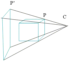
Features of the perspective projection:
-
does not preserve proportions;
-
does not preserve parallel lines;
-
object size depends on the closeness to the center: close objects seem
big, distant objects seem small;
-
gives a good impression of image depth;
-
contains a vanishing point, where all the lines that are perpendicular
to the projection plane converge; this point is the orthogonal
projection of C on the plane p. It also represents the infinity point
(the horizon).
-
often used for painting, drawing (especially comics), and 3D software.
Projection in OpenGL
-
2D parallel orthographic:
gluOrtho2D(left, right, bottom, top);
-
3D parallel orthographic:
glOrtho(left, right, bottom, top, near, far);
-
3D perspective
glFrustum(xmin, xmax, ymin, ymax, near, far); // camera view
gluPerspective(angle, aspect, near, far);
Camera
- For both the parallel and perspective projections, defining the view
area is not enough. We also need to position the camera in the scene.
- Camera location and orientation (page 252 in the textbook):
- gluLookAt(eyex, eyey, eyez, atx, aty, atz, upx, upy, upz);
3D Transformations
Def. A function F : R3 ->
R3 such that Po(xo,
yo, zo) -> P(x, y, z).
Homogeneous coordinates: represent each point as a vector with
4 coordinates.
Every transformation can be represented as a 4x4 matrix.
| P = |
 |
x
y
z
1 |
 |
Translation of vector Tv=(tx, ty,
tz)
 |
x
y
z
1 |
 |
=
|
 |
1
0
0
0 |
0
1
0
0 |
0
0
1
0 |
tx
ty
tz
1 |
  |
xo
yo
zo
1 |
 |
In OpenGL:
glTranslatef(xt, yt, zt);
glTranslated(xt, yt, zt);
Scaling of factors Sv=(sx, sy,
sz)
 |
x
y
z
1 |
 |
=
|
 |
sx
0
0
0 |
0
sy
0
0 |
0
0
sz
0 |
0
0
0
1 |
  |
xo
yo
zo
1 |
 |
In OpenGL:
glScalef(sx, sy, sz);
glScaled(sx, sy, sz);
Rotation: more complex than in 2D.
Around the 0x axis of angle q :
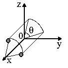 |
 |
x
y
z
1 |
 |
=
|
 |
1
0
0
0 |
0
cos q
sin q
0 |
0
- sin q
cos q
0 |
0
0
0
1 |
  |
xo
yo
zo
1 |
 |
Around the 0y axis of angle q :
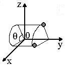 |
 |
x
y
z
1 |
 |
=
|
 |
cos q
0
sin q
0 |
0
1
0
0 |
- sin q
0
cos q
0 |
0
0
0
1 |
  |
xo
yo
zo
1 |
 |
Around the 0z axis of angle q :
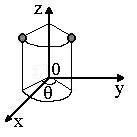 |
 |
x
y
z
1 |
 |
=
|
 |
cos q
sin q
0
0 |
- sin q
cos q
0
0 |
0
0
1
0 |
0
0
0
1 |
  |
xo
yo
zo
1 |
 |
Any arbitrary rotation about the origin R can be expressed as a unique
product (composition) of a rotation about two of the 3 axes. For example:
R = Rx Rz.We can determine the rotation matrix for
R by multiplying the rotation matrix for Rx with the rotation
matrix for Rz.
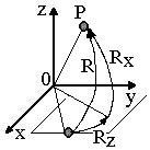 In OpenGL: In general, defined by an angle and an axis:
glRotatef(angle, vx, vy, vz);
glRotated(angle, vx, vy, vz);
Example: rotate around Oy, by an angle of 30o:
glRotatef(30.0, 0.0, 1.0, 0.0);
Composing the transformations
-
Rotations are not commutative: Rx · Rz¹
Rz · Rx.
-
Translations and rotations are not commutative: R · T ¹
T · R.
-
Translations are commutative: T1 · T2 = T2
· T1.
-
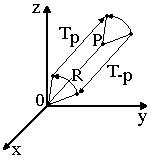
Rotation about an arbitrary point P: Tp · R ·
T-p:
Projection as Transformation
-
Both the parallel and the perspective projections can be written as 4x4
matrixes.
-
To apply the perspective projection, one can first transform the object,
then apply the parallel projection.
Matrix Mode in OpenGL
- There are 3 matrices in OpenGL,
- for the objects in the scene (model view),
- for the camera (point of view or projection),
- for the texture.
- Only one of them is active at any time.
- All of the transformations are defined as matrices that are
multiplied with the active matrix.
Matrix Operations
- Switching the matrix mode:
glMatrixMode(GL_PROJECTION);
glMatrixMode(GL_MODELVIEW); // default
glMatrixMode(GL_TEXTURE);
- Setting a matrix to the identity:
glLoadIdentity();
- Loading a particular matrix:
glFloat m[] = {1.0, 0.0, ... }; // 16 elem.
glLoadMatrixf(m); // f or d
- Multipling the active matrix by a given matrix
glMultMatrixf(m); // f or d
- The 3 matrices are organized in a stack. One can push the active
matrix in the stack, then pop it out of the stack again.
glPushMatrix(); // save
glPopMatrix(); // restore


