
In this lab, we will do an introduction to 3D modeling using Blender. We will create a bee creature looking approximately like this:

This lab assumes that you have installed Blender version 4.2.1 or .2 LTS. You can find it at www.blender.org.
Open Blender and click to set the preferences if this is the first time, then click outside the new file dialog to close it. The editor should show a 3D space with a cube in the center. Save it as bee.blend. Make sure to save it from time to time.
If you don't see a cube in the scene, from the File menu create a new file of type General. You can also add a cube from the Add menu (top, second row) - Mesh - Cube.
Here are some navigation controls for you to try out:
Let's create the body of the bee, including the head. With the cube selected, from the top left of the window, click on Object Mode and switch to Edit Mode:
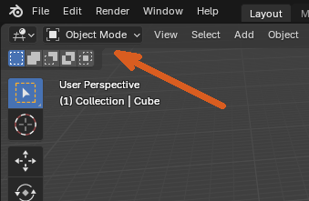
You should now see the vertices of the object, and all of them should be selected.
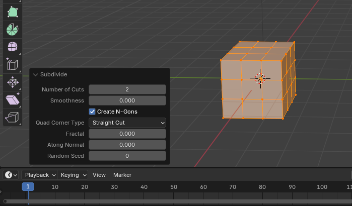
Subdivide
From the toolbar at the top on the second row, click on
the Edge menu, and select Subdivide. In the bottom
left corner, a label showing Subdivide should appear. Click
on the arrow on it to expand it, then set the number of cuts to
2. Here is the result below (right):
Rounding the cube
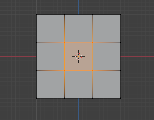
Click outside the object to deselect all the vertices. Then switch
to the front view (-Y in the gizmo) and click and drag to select the
inner rectangle in the face:
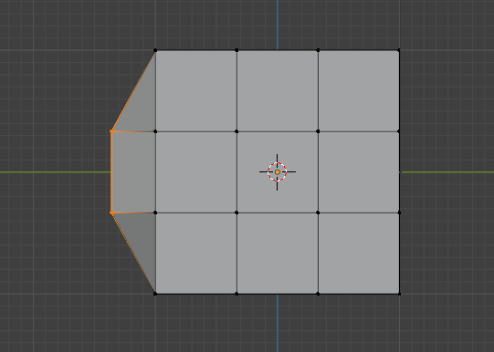
Switch to the right side view (X) and hit G to move the selected vertices. Hit Y to constrain the movement to the Y axis. Move the vertices to the left about half the length of a rectangle:
Turn on the "X-ray" feature with Alt-Z. Now in the same view, select the inner rectangle on this side. You can use the mouse to rotate the view around. You should notice that these rectangles were selected both on the left and on the right side:
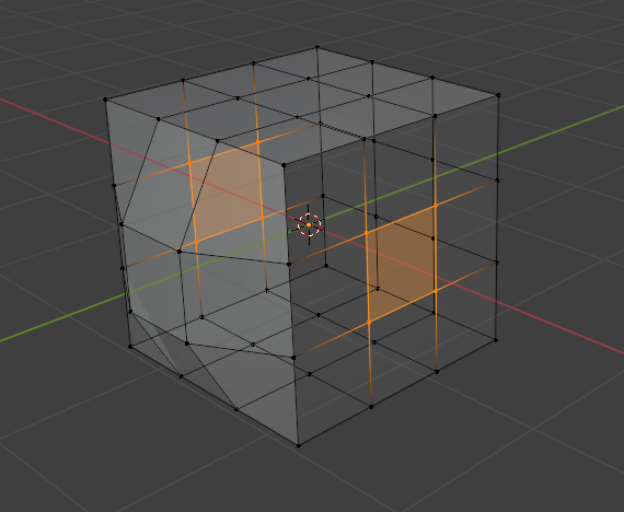
Switch again to the Front view (-Y). Hit S for scale, then X to constrain it to that axis, then pull the mouse to scale this set of rectangles by about the same amount:

Now repeat the procedure for the top and bottom faces, restraining the scale to the Z axis:
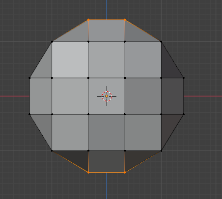
Turn the X-Ray off with Alt-Z. Switch to the front view (-Y). Select the 4 out-most corners by clicking on the first one, then hold the shift while clicking on the others. Then from the Vertex menu in the top toolbar, second row, select Smooth Vertices. This should round up that face:
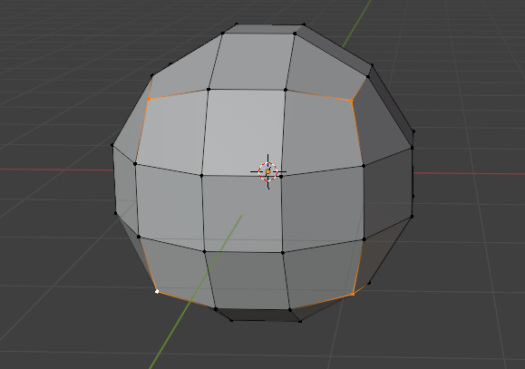
Repeat the procedure for the back face. Then without deselecting them, switch to the Right view, the hit G followed by Y to move them on the Y axis, and align them vertically as best you can with the other vertices on the back face. This is now the head of the bee.
Extrude
Next, we'll use the extrude functionality to create the body of
the bee. Switch to the back view (Y). Make sure you are not in
X-ray mode. Select the inner rectangle, then hit Delete.
Select the 4 original corners of this face and use the scale over x and z to bring them a little closer to the center to round up the outline of the face some more.
Then select the border of this face by holding the Alt key and left-clicking on one of the edges:
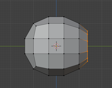
Switch to the right view and zoom out a little. With this border still selected, hit E to extrude it, Y to constrain it to this axis, and them pull the extruded vertices a little to the right. Use the scale to scale if down a little. This will be the connection point between the head and the thorax.
Use the same procedure to create the thorax and then the body of the bee. You can follow the profile at the top. For the last half of the body, you can also pull the extruded vertices down after the operation to make it curve towards the floor. After all these operations, the bee should look approximately like this:
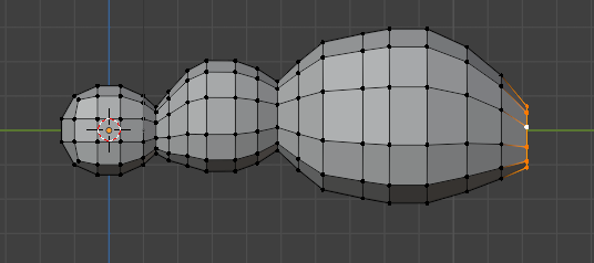
If you wish to adjust any of the rings you created this way after the fact, you can use Alt-Click for it.
Let's close the last created ring in the back. Switch to the back view (Y) and zoom in. Select the top two vertices. Then hit F to create a face using them. This should connect them to the next two below. Without changing the selection, hit F repeatedly until the whole ring is covered by these new faces:
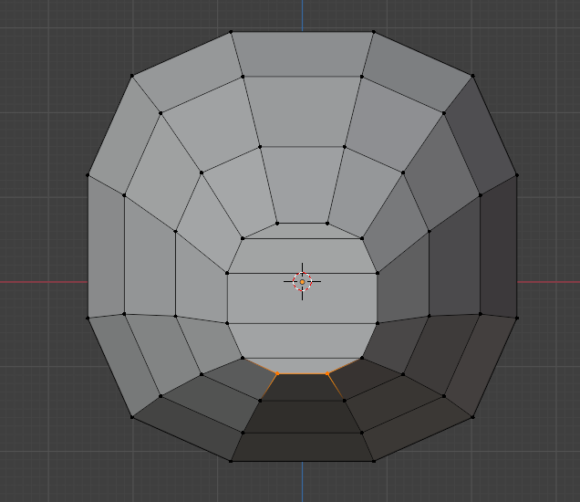
Now, we would like to cut the faces vertically to make the entire structure symmetric. For this we'll use a tool called Knife, or K.
Hit K and click on one of the vertices at the top. Then move down and click on the corresponding vertex at the bottom. After that, hit Enter to finish the cut. Repeat the operation to connect each vertex from the top with one at the bottom:

You can round up the last face by selecting the vertices in the middle and pulling them out over Y, then smoothing the intermediate ones.
Before we add more body parts, let's paint the body of the bee. From the top left corner of the window, switch from Edit Mode to Vertex Paint Mode.
First, click on the white rectangle next to Draw and select a nice yellow-gold color. Click and drag the mouse over all the vertices to color them in this color. You'll need to rotate the view around and paint it from several angles to get all of them.
Then change the color to a dark brown and color a few of the rings in that color to create the stripes on the bee:
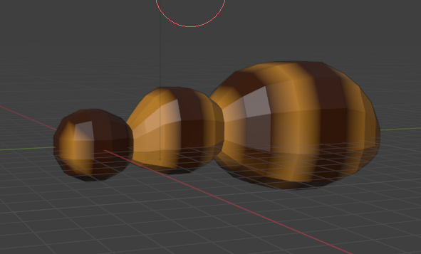
Let's set the camera so that we can see the entire bee when we render the image. First, click on the camera button below the gizmo to toggle the camera view. Then click on the button below that looking like a paddle lock, to toggle navigation in the camera view. Zoom out and use the mouse scroll button to bring the bee well into view:
If we try to render the object, the colors will not show up yet. Switch back to Object Mode in the top left corner of the editor.
On the right side of the window, there is a vertical toolbar with multiple options. Click on Material almost at the bottom:
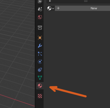
Then click New to add a new material to it.
In the same toolbar, close to the top, click on Render. Switch the Render Engine to Cycles.
Now click on Shading at the top of the window and zoom in on the lower part of the window to see it better. In this panel, you can link different things into the way the color is rendered. In the panel's menu, click Add to add a new node, select Input and choose Color Attribute from the options. Then click in the panel to the left of the exiting nodes to place it there. At the bottom of this node, click on the text box and select Attribute or Col or whatever option you see there (this is the name of the vertex paint). Then create a link from the Color of this node to the Base Color of the material, as you can see below.
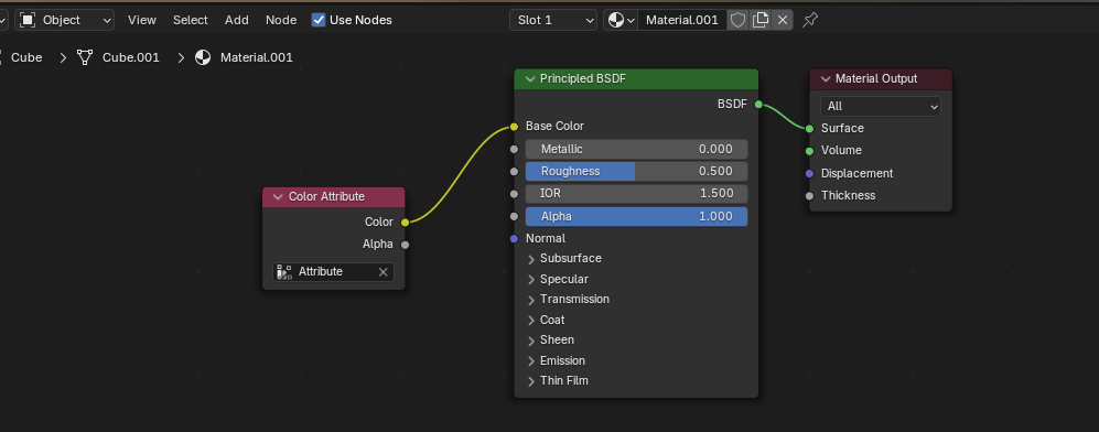
If you've done this right, the bee shown above this panel should now display the colors. Save the file and click on Layout at the top again to go back to the previous view.
Now you can try rendering the image. Just click on the Render menu at the top of the window and select Render Image. You can close the rendering scene one you have seen the result. Note that it does the rendering in several cycles, so if you wait a little, the image might improve.
Turn the X-Ray on (Alt-z). From the Add menu, select Curve and then Bezier. This will probably be inside the bee's head, that's why we need the X-Ray. In the options panel that appears on the bottom left, switch the radius to 2m and the rotation over Y and Z to 90 degrees. This should make it look approximately like the outline of a right front leg (on the left of the screen).
Turn the X-Ray off and move the leg to the right shoulder of the bee (with G):
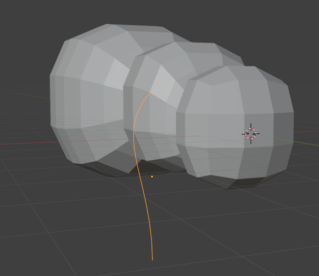
Switch from Object mode to Edit mode and select the tangent to the top point and pull it up with the G key to make the shoulder part of the leg more curvy. Then switch back to Object mode.
In the vertical toolbar on the right side, click on Data that is just above Material. Expand Geometry and under Bevel, set a depth of 0.1m (hit Enter after typing the number) and check the option to Fill Caps. This will create a thin tub around the leg. Then from the top menu, second row, click on Object and select Convert and then Mesh.
Switch Edit Mode to see the change that happened to this object. Then switch to Vertex Paint and color the leg in some dark color. In the Material tab in the vertical toolbar on the right, instead of adding a new material to this object, also set its material to the one created to the bee body (Material.001).
Duplicate and Mirror Object
Switch back to Object Mode. With the leg selected, from the Object menu, select Duplicate Object. Move the copied object to the other side of the body. Without deselecting the new object, from the Object menu, choose Mirror and then X Global. Use the top view to place the second leg a little better, then rotate (R) both of them a little in the top view so that they're facing more towards the front. Then use the front view to align them with each other vertically:
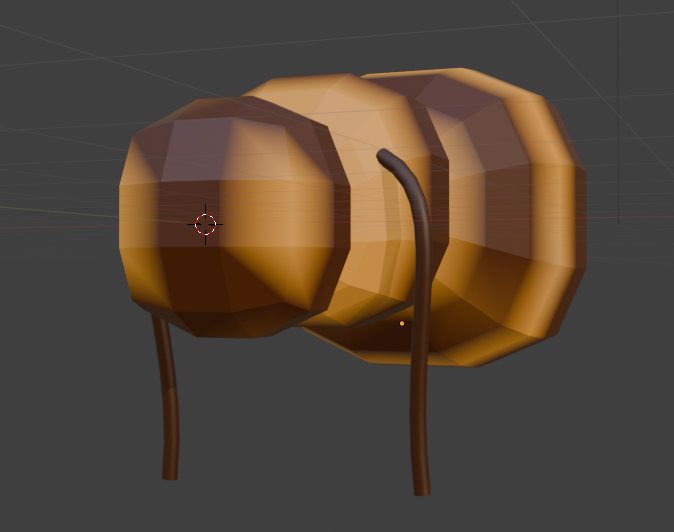
Add 4 more legs and antennas to the bee using similar procedures. Then add two wings starting from an object of type Circle added from the Mesh category. Use scale or edit the points directly to create the outline of one wing. Use Fill (F) or Grid Fill (Edit mode, Face menu) to make a face out of the wing vertices. Extrude it once to give it a bit of depth. Color it however you see fit. Then duplicate it and mirror the result to have a similar second wing.
In Object mode, you can try Shade Smooth from the Object menu to see if you prefer that option. I recommend using a flat shading while you're editing the object and switching to smooth at the end.
Render the image once you are happy with the result and save it as a png or jpg.
Turn in: the file bee.blend and the rendered image file.